Кривошипно-шатунный механизм двигателя: устройство, назначение, как работает
Содержание
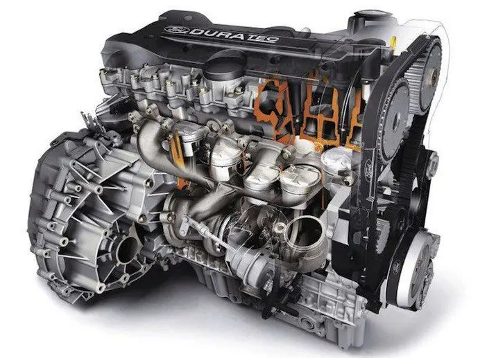
В двигателях внутреннего сгорания существует два механизма, благодаря которым возможно перемещение транспорта. Это газораспределительный и кривошипно-шатунный. Сосредоточимся на назначении КШМ и его устройстве.
Что такое кривошипно-шатунный механизм двигателя
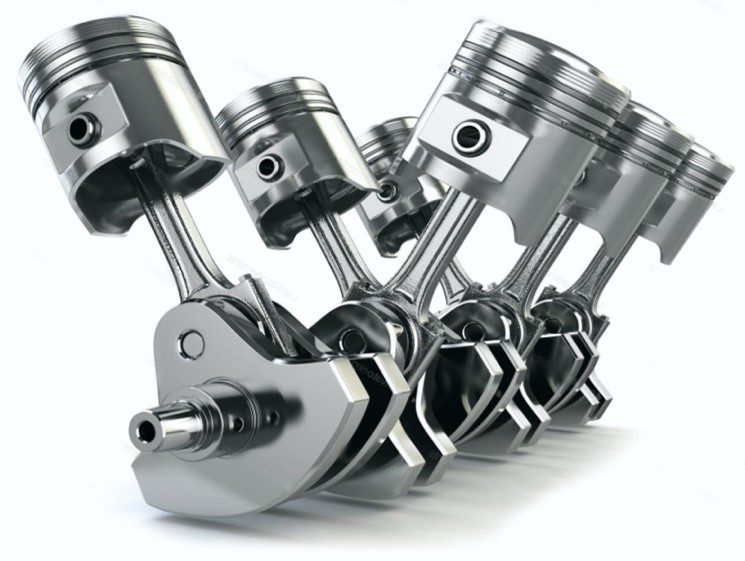
Под КШМ подразумевается комплект запчастей, образующих единый агрегат. В нем смесь из топлива и воздуха в определенной пропорции сгорает и выделяет энергию. Механизм состоит из двух категорий подвижных деталей:
- Выполняющие линейные движения – поршень перемещается вверх/вниз в цилиндре;
- Выполняющие вращательные движения – коленчатый вал и детали, установленные на нем.
Узел, соединяющий оба типа деталей, способен преобразовать один вид энергии в другой. Когда мотор работает автономно, распределение сил идет от двс к ходовой части. Некоторые автомобили позволяют перенаправить энергию обратно – от колес к мотору. Необходимость в этом может возникнуть, например, при невозможности запустить двигатель от аккумулятора. Механическая трансмиссия позволяет завести машину с толкача.
Для чего нужен кривошипно-шатунный механизм двигателя
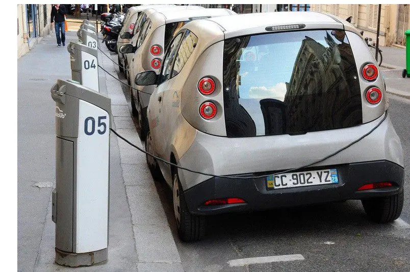
КШМ приводит в движение другие механизмы, без которых невозможно было бы машине ехать. В электротранспорте электрический мотор благодаря энергии, которую он получает от батареи, сразу создает вращение, поступающее на вал трансмиссии.
Недостаток электрических агрегатов в том, что у них маленький запас хода. Хотя ведущие производители электромобилей и повысили эту планку до нескольких сотен километров, подавляющему большинству автомобилистов такой транспорт недоступен по причине его дороговизны.
Единственным дешевым решением, благодаря которому возможно передвижение на большие расстояния и с большой скоростью, является автомобиль, оснащенный ДВС. В нем используется энергия взрыва (а точнее расширения после него), чтобы приводить в движение детали цилиндропоршневой группы.
Назначение КШМ в том, чтобы обеспечить равномерное вращение коленчатого вала при прямолинейном перемещении поршней. Идеального вращения пока невозможно достичь, однако существуют модификации механизмов, которые минимизируют рывки, образующиеся при резких толчках поршней. Примером тому служат 12-цилиндровые двигатели. Угол смещения кривошипов в них минимален, а срабатывание всей группы цилиндров распределено на большее количество интервалов.
Принцип работы кривошипно-шатунного механизма
Если описать принцип работы данного механизма, то его можно сравнить с процессом, который происходит во время езды на велосипеде. Велосипедист поочередно нажимает на педали, приводя во вращение ведущую звездочку.
Линейное движение поршня обеспечивается сгоранием ВТС в цилиндре. Во время микровзрыва (ВТС в момент подачи искры сильно сжато, поэтому и образуется резкий толчок) газы расширяются, выталкивая деталь в крайнее нижнее положение.
Шатун связывается с отдельным кривошипом на коленчатом валу. Инерция, а также идентичный процесс, происходящий в смежных цилиндрах, обеспечивают вращение коленвала. Поршень не замирает в крайних нижней и верхней точках.
Вращающийся коленчатый вал связан с маховиком, к которому подсоединяется фрикционная поверхность коробки передач.
После завершения такта рабочего хода для выполнения других тактов мотора поршень приводится в движение уже за счет оборотов вала механизма. Оно возможно благодаря выполнению такта рабочего хода в смежных цилиндрах. Чтобы минимизировать рывки, шатунные шейки кривошипов смещены относительно друг друга (есть модификации с рядным размещением шеек).
Устройство КШМ
Кривошипно-шатунный механизм включает большое количество деталей. Условно их можно отнести к двум категориям: выполняющие движение и те, которые все время остаются зафиксированными на одном месте. Одни выполняют разного рода движения (поступательные или вращательные), а другие служат формой, в которых обеспечивается аккумулирование нужной энергии или опорой для этих элементов.
Вот какие функции выполняют все элементы кривошипно-шатунного механизма.
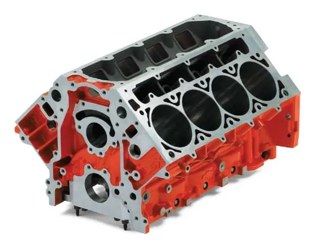
Блок-картер
Отлитый из прочного металла (в бюджетных авто – чугун, а в более дорогих – алюминиевый или другой сплав) блок. В нем сделаны необходимые отверстия и каналы. По каналам циркулирует охлаждающая жидкость и моторное масло. Технические отверстия позволяют соединить ключевые элементы мотора в одну конструкцию.
Самые большие отверстия – сами цилиндры. В них помещаются поршни. Также конструкция блока имеет опоры для опорных подшипников коленвала. В ГБЦ располагается газораспределительный механизм.
Использование чугуна или алюминиевого сплава обусловлено тем, что этот элемент должен выдерживать большие механические и термические нагрузки.
В нижней части картера расположен поддон, в котором скапливается масло после смазки всех элементов. Чтобы в полости не создавалось чрезмерное давление газов, конструкция имеет вентиляционные каналы.
Существуют автомобили с мокрым или сухим картером. В первом случае масло собирается в поддоне и остается в нем. Этот элемент является резервуаром для забора и хранения смазки. Во втором случае масло стекает в поддон, но насос откачивает его в отдельный бачок. Такая конструкция предотвратит полную потерю масла при пробое поддона – вытечет лишь небольшая часть смазки после того, как мотор будет заглушен.
Цилиндр
Цилиндр – еще один неподвижный элемент мотора. По сути, это отверстие со строгой геометрией (поршень должен идеально помещаться в него). Они также относятся к цилиндропоршневой группе. Однако в кривошипно-шатунном механизме цилиндры выполняют функцию направляющих. Они обеспечивают строго выверенное перемещение поршней.
Размеры данного элемента зависят от особенностей мотора и величины поршней. Стенки в верху конструкции сталкиваются с максимальной температурой, какая только может возникать в двигателе. Также в так называемой камере сгорания (надпоршневое пространство) происходит резкое расширение газов после воспламенения ВТС.
Для предотвращения чрезмерного износа стенок цилиндров при высоких температурах (в некоторых случаях она может резко повышаться до 2 500 градусов) и большого давления, они смазываются. Между уплотнительными кольцами и цилиндром образуется тонкая масляная пленка, предотвращающая контакт металлических частей. Еще для снижения силы трения внутренняя поверхность цилиндров обрабатывается специальным составом, и полируется до идеальной степени (поэтому поверхность называется зеркалом).
Существует два типа цилиндров:
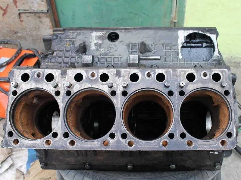
- Сухой тип. В основном в машинах используются именно такие цилиндры. Они являются частью блока и выглядят в виде отверстий, сделанных в корпусе. Чтобы металл охлаждался, с внешней стороны цилиндров сделаны каналы для циркуляции охлаждающей жидкости (рубашка двс);
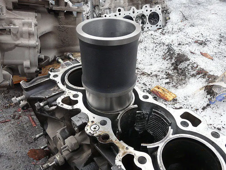
- Мокрый тип. В этом случае цилиндры будут отдельно выполненными гильзами, которые вставляются в отверстия блока. Они надежно уплотняются, чтобы в процессе работы агрегата не образовывались дополнительные вибрации, из-за чего детали КШМ будут выходить из строя слишком быстро. Такие гильзы с внешней стороны контактируют с ОЖ. Подобная конструкция мотора более податлива ремонту (например, при образовании глубоких царапин гильзу просто меняют, а не растачивают и шлифуют отверстия блока во время капиталки мотора).
В V-образных моторах часто цилиндры не расположены симметрично относительно друг друга. Это обусловлено тем, что один шатун обслуживает один цилиндр, и он имеет отдельное место на коленвале. Однако есть и модификации с двумя шатунами на одной шатунной шейке.
Блок цилиндров
Это самая большая часть конструкции мотора. Вверху этого элемента устанавливается головка блока цилиндров, а между ними находится прокладка (зачем она нужна и как определить ее неисправность, читайте в отдельном обзоре).
В головке блока цилиндров сделаны углубления, которые формируют особенную полость. В ней сжатая воздушно-топливная смесь воспламеняется (часто ее называют камерой сгорания). Модификации моторов на водяном охлаждении будут оснащаться головкой с каналами для циркуляции жидкости.
Остов двигателя
Все неподвижные части КШМ, соединенные в одну конструкцию, называются остовом. Эта часть воспринимает основную силовую нагрузку в процессе работы подвижных частей механизма. В зависимости от того, как закреплен двигатель в моторном отсеке, остов воспринимает также нагрузки и от кузова или рамы. В процессе движения эта часть также сталкивается с воздействием трансмиссии и ходовой части машины.
Чтобы предотвратить перемещение ДВС во время разгона, торможения или маневрирования, остов крепко фиксируется болтами к несущей части транспортного средства. Для устранения вибраций на месте соединения используются подушки двигателя, сделанные из резины. Их форма зависит от модификации двигателя.
Когда машина перемещается по неровной дороге, на кузов оказывается нагрузка кручения. Чтобы мотор не воспринимал такие нагрузки, обычно его крепят в трех точках.
Все остальные части механизма являются подвижными.
Поршень
Входит в состав поршневой группы КШМ. Форма поршней тоже может разниться, но ключевой момент – они выполнены в виде стакана. Верхнюю часть поршня называют головкой, а нижнюю – юбкой.
Головка поршня – самая толстая часть, так как она воспринимает на себя термическую и механическую нагрузку при воспламенении топлива. Торец того элемента (днище) может иметь разную форму – плоскую, выпуклую или вогнутую. Эта часть формирует размеры камеры сгорания. Нередко встречаются модификации с углублениями разной формы. Все эти типы детали зависят от модели ДВС, принципа подачи топлива и т.д.
По бокам поршня сделаны канавки для установки уплотнительных колец. Ниже этих проточек имеются углубления для отвода масла от детали. Юбка чаще всего имеет форму овала, и основная ее часть – направляющая, предотвращающая клин поршня в результате термического расширения.
Чтобы компенсировать силу инерции, поршни изготавливаются из легкосплавных материалов. Благодаря этому они имеют небольшой вес. Днище детали, также как стенки камеры сгорания, сталкиваются с максимальными температурами. Однако данная деталь не охлаждается при помощи циркуляции ОЖ в рубашке. Из-за этого алюминиевый элемент подвержен сильному расширению.
Для предотвращения заклинивания поршень охлаждается маслом. Во многих моделях авто смазка подается естественным путем – масляный туман оседает на поверхности и стекает обратно в поддон. Однако встречаются двигатели, в которых масло подается под напором, обеспечивая лучший теплоотвод от нагретой поверхности.
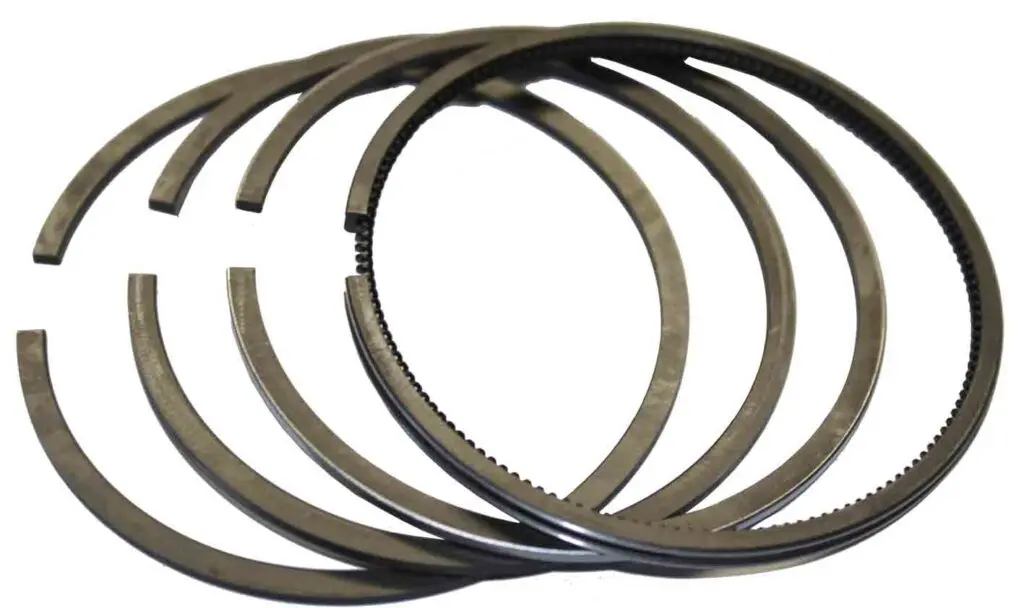
Поршневые кольца
Поршневое кольцо выполняет свою функцию в зависимости от того, в какой части головки поршня оно установлено:
- Компрессионные – самые верхние. Они обеспечивают уплотнение между стенками цилиндра и поршня. Их назначение – не дать газам из надпоршневого пространства проникнуть в картер. Чтобы облегчить установку детали, в ней сделан разрез;
- Маслосъемные – обеспечивают удаление излишка масла со стенок цилиндра, а также предотвращают проникание смазки в надпоршневое пространство. Эти кольца имеют специальные канавки, облегчающие отвод масла к дренажным проточкам поршня.
Диаметр колец всегда больше диаметра цилиндра. Благодаря этому они обеспечивают уплотнение в цилиндропоршневой группе. Чтобы ни газы, ни масло не просачивались через замки, кольца размещаются на своих местах со смещением прорезей относительно друг друга.
Материал, который используется для изготовления колец, зависит от их применения. Так, компрессионные элементы чаще всего выполнены из чугуна высокой прочности и минимальным содержанием примесей, а маслосъемные – из высоколегированной стали.
Поршневой палец
Эта деталь позволяет закрепить поршень на шатуне. Выглядит он в виде полой трубки, которая помещается под головкой поршня в бобышки и одновременно через отверстие головки шатуна. Чтобы палец не смещался, его фиксируют стопорными кольцами с обеих сторон.
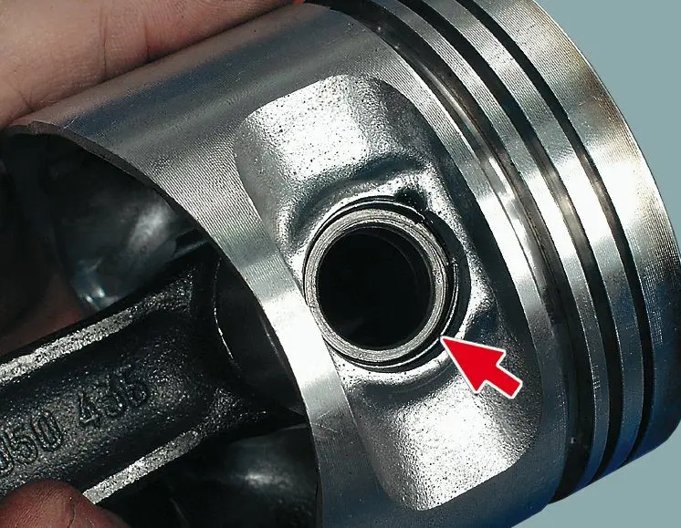
Подобная фиксация позволяет пальцу свободно проворачиваться, что снижает сопротивление движению поршня. Это также предотвращает образование выработки лишь на месте крепления в поршне или шатуне, что значительно продлевает рабочий ресурс детали.
Для предотвращения износа вследствие силы трения деталь изготавливают из стали. А для большей устойчивости к термическим нагрузкам ее изначально закаляют.
Шатун
Шатун представляет собой толстую тягу с ребрами жесткости. С одной стороны в нем имеется поршневая головка (отверстие, в которое вставляется палец поршня), а с другой – книвошипная головка. Второй элемент является разборным, чтобы деталь можно было снять или установить на шейку кривошипа коленчатого вала. В нем имеется крышка, которая крепится к головке при помощи болтов, а для предотвращения преждевременного износа деталей, в него устанавливается вкладыш с отверстиями для смазки.
Вкладыш нижней головки называется шатунным подшипником. Он выполнен из двух стальных пластин с выгнутыми усиками для фиксации в головке.

Чтобы снизить силу трения внутренней части верхней головки, в нее запрессовывается бронзовая втулка. Если она износится, не нужно будет менять весь шатун. Во втулке имеются отверстия для подачи масла на палец.
Существует несколько модификаций шатунов:
- Бензиновые моторы чаще всего оснащаются шатунами с расположением разъема головки под прямым углом относительно оси шатуна;
- Дизельные ДВС имеют шатуны с косым разъемом головки;
- V-образные двигатели нередко оснащаются спаренными шатунами. Второстепенный шатун второго ряда фиксируется на основном при помощи пальца по тому же принципу, что и к поршню.
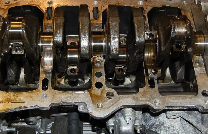
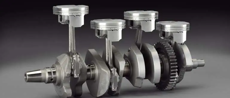
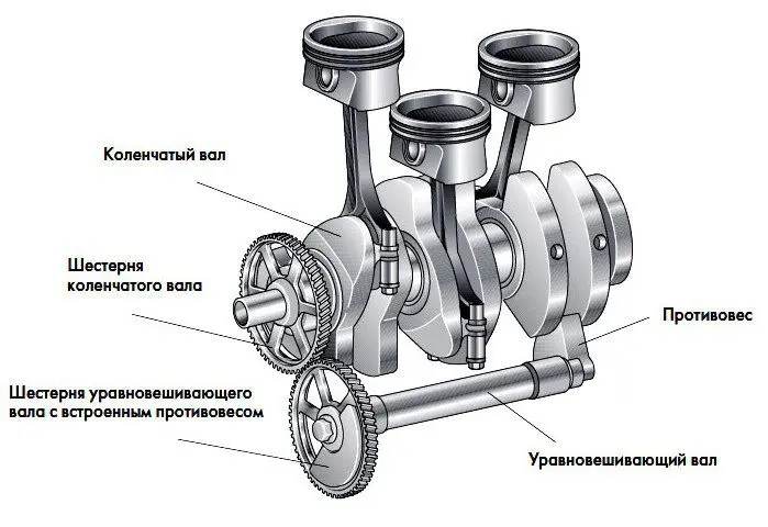
Коленчатый вал
Этот элемент состоит из нескольких кривошипов со смещенным расположением шатунных шеек относительно оси коренных шеек. О разных типах коленвалов и их особенностях уже есть отдельный обзор.
Назначение этой детали – преобразовать поступательное движение от поршня во вращательное. Шатунная шейка кривошипа соединяется с нижней головкой шатуна. В двух или нескольких местах коленвала имеются коренные подшипники, предотвращающие образование вибрации вследствие несбалансированного вращения кривошипов.
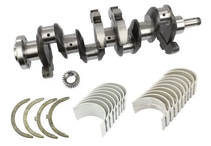
Большинство коленчатых валов оснащены противовесами, гасящими центробежные силы, действующие на коренные подшипники. Деталь изготавливается путем литья или вытачивается на токарных станках из единой болванки.
На носке коленвала крепится шкив, который приводит в движение газораспределительный механизм и другое оборудование, например, помпу, генератор и привод кондиционера. На хвостовике имеется фланец. К нему крепится маховик.
Маховик
Деталь, имеющая форму диска. О формах и типах разных маховиков и об их отличиях также посвящена отдельная статья. Он необходим для преодоления сопротивления сжатия в цилиндрах, когда поршень выполняет такт сжатия. Это обеспечивается благодаря инерции вращающегося чугунного диска.
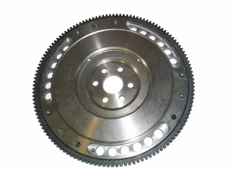
На торце детали зафиксирован зубчатый венец. К нему подсоединяется шестеренка бендикса стартера в момент запуска мотора. Со стороны, противоположной фланцу, поверхность маховика соприкасается с диском сцепления корзины трансмиссии. Максимальная сила трения между этими элементами обеспечивает передачу крутящего момента на вал коробки передач.
Как видно, кривошипно-шатунный механизм имеет сложное устройство, из-за чего ремонт агрегата должен выполняться исключительно профессионалами. Чтобы продлить ресурс двигателя, крайне важно придерживаться регламента планового технического обслуживания авто.
Дополнительно посмотрите видеообзор о КШМ:
Вопросы и ответы:
Какие детали входят в кривошипно шатунный механизм? Неподвижные детали: блок цилиндров, головка блока, гильзы цилиндров, вкладыши и коренные подшипники. Подвижные детали: поршень с кольцами, палец поршня, шатун, коленвал и маховик.
Как называется эта деталь КШМ? Это кривошипно-шатунный механизм. Он преобразует возвратно-поступательные движения поршней в цилиндрах во вращательные движения коленвала.
Какую функцию выполняют неподвижные детали КШМ? Эти детали отвечают за точное направление подвижных деталей (например, вертикальное перемещение поршней) и надежную фиксацию их для вращения (например, коренные подшипники).