Газораспределительный механизм — клапанная группа
Содержание
Назначение и виды ГРМ:
1.1. Назначение механизма газораспределения:
Назначение механизма газораспределения — пропускать свежую топливную смесь в цилиндры двигателя и выпускать выхлопные газы. Газообмен осуществляется через впускные и выпускные отверстия, которые герметично закрываются элементами ремня ГРМ в соответствии с принятым порядком работы двигателя.
1.2. Назначение клапанной группы:
назначение клапанной группы — герметично закрыть впускные и выпускные отверстия и открыть их в указанное время на указанное время.
1.3. Типы ГРМ:
в зависимости от органов, которыми цилиндры двигателя связаны с окружающей средой, ГРМ бывает клапанным, золотниковым и комбинированным.
1.4. Сравнение типов ГРМ:
фаза газораспределения является наиболее распространенным благодаря относительно простому устройству и надежной работе. Идеальная и надежная герметизация рабочего пространства, достигаемая благодаря тому, что клапаны остаются неподвижными при высоком давлении в цилиндрах, дает серьезное преимущество перед затвором или комбинированным ГРМ. Поэтому все чаще используются фазы газораспределения.

Устройство клапанной группы:
2.1. Устройство клапанов:
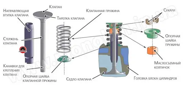
Клапаны двигателя состоят из штока и головки. Головки чаще всего делают плоской, выпуклой или колоколообразной формы. Головка имеет небольшой цилиндрический пояс (около 2 мм) и уплотнительную фаску под углом 45˚ или 30˚. Цилиндрическая лента позволяет, с одной стороны, сохранить основной диаметр клапана при шлифовании уплотнительной фаски, а с другой стороны, повысить жесткость клапана и тем самым предотвратить деформацию. Наибольшее распространение получили клапаны с плоской головкой и уплотнительной фаской под углом 45˚ (таковы чаще всего впускные клапаны), а для улучшения наполнения и очистки цилиндров впускной клапан имеет больший диаметр, чем выпускной клапан. Выхлопные клапаны часто делают с выпуклой головкой в форме шара.
Это улучшает отток выхлопных газов из цилиндров, а также увеличивает прочность и жесткость клапана. Чтобы улучшить условия отвода тепла от головки клапана и увеличить общую недеформируемость клапана, переход между головкой и штоком выполнен под углом 10˚ — 30˚ и с большим радиусом кривизны. На верхнем конце стержня клапана выполняются пазы конической, цилиндрической или специальной формы в зависимости от принятого способа крепления пружины к клапану. Натриевое охлаждение используется в ряде двигателей для снижения тепловой нагрузки на разрывные клапаны. Для этого клапан делают полым, а образовавшуюся полость наполовину заполняют натрием, температура плавления которого составляет 100˚С. Когда двигатель работает, натрий плавится и, перемещаясь в полости клапана, передает тепло от горячей головки к штоку охладителя, а оттуда к приводу клапана.
2.2. Подсоединение клапана к его пружине:
конструкции этого агрегата чрезвычайно разнообразны, но наиболее распространена конструкция с полуконусами. С помощью двух полуконусов, которые входят в каналы, выполненные в стержне клапана, прижимается пластина, которая удерживает пружину и не позволяет разобрать агрегат. Это создает соединение между пружиной и клапаном.
2.3. Расположение седла клапана:
во всех современных двигателях выхлопные седла изготавливаются отдельно от головки блока цилиндров. Такие седла также используются для присосок, когда головка блока цилиндров изготовлена из алюминиевого сплава. Когда он чугун, седла делают прямо в нем. Конструктивно седло представляет собой кольцо, которое крепится к головке блока цилиндров в специально обработанном гнезде. При этом на внешней поверхности седла иногда делают канавки, которые при надавливании на седло заполняются материалом ГБЦ, обеспечивая тем самым их надежное крепление. Кроме прижима, застегивание можно производить также взмахом седла. Для обеспечения герметичности рабочего пространства при закрытом клапане рабочая поверхность седла должна быть обработана под тем же углом, что и уплотнительная фаска головки клапана. Для этого седла обрабатываются специальными инструментами с углами заточки не 15 not, 45˚ и 75˚, чтобы получить уплотнительную ленту под углом 45˚ и шириной около 2 мм. Остальные углы сделаны для улучшения обтекания седла.
2.4. Расположение направляющих клапана:
конструкция направляющих очень разнообразна. Чаще всего используются направляющие с гладкой внешней поверхностью, которые изготавливаются на бесцентровом сантехническом станке. Направляющие с внешним удерживающим ремнем удобнее застегивать, но сложнее сделать. Для этого целесообразнее вместо ремня сделать в направляющей канал для ограничительного кольца. Направляющие выпускных клапанов часто используются для защиты их от окислительного действия потока горячих выхлопных газов. В этом случае делают более длинные направляющие, остальная часть которых располагается в выпускном канале ГБЦ. По мере уменьшения расстояния между направляющей и головкой клапана отверстие в направляющей на стороне головки клапана сужается или расширяется в области головки клапана.
2.5. Устройство рессор:
в современных двигателях наиболее распространены цилиндрические рессоры с постоянным шагом. Для формирования опорных поверхностей концы витков пружины сводятся до упора друг в друга и притирки их лобами, в результате чего общее количество витков в два-три раза больше, чем количество рабочих пружин. Концевые катушки опираются на одну сторону пластины и на другую сторону головки цилиндров или блока. при опасности возникновения резонанса пружины клапанов изготавливаются с переменным шагом. Ступенчатый редуктор изгибается либо от одного конца пружины к другому, либо от середины к обоим концам. При открытии клапана ближайшие друг к другу обмотки соприкасаются, в результате чего количество рабочих обмоток уменьшается, а частота свободных колебаний пружины увеличивается. Это устраняет условия для резонанса. С этой же целью иногда используются конические пружины, частота собственных колебаний которых варьируется по их длине и возникновение резонанса исключено.
2.6. Материалы для изготовления элементов клапанной группы:
• Клапаны — всасывающие клапаны изготавливаются из хрома (40x), хромоникеля (40XN) и других легированных сталей. Выпускные клапаны изготовлены из жаропрочных сталей с повышенным содержанием хрома, никеля и других легирующих металлов: 4Х9С2, 4Х10С2М, Х12Н7С, 40СХ10МА.
• Седла клапана — используются жаропрочные стали, легированный чугун, алюминиевая бронза или металлокерамика.
• Направляющие клапана — сложные условия, в которых они работают, для изготовления и требуют использования материалов с высокой термической и износостойкостью и хорошей теплопроводностью, таких как серый перлитный чугун и алюминиевая бронза.
• Пружины — изготавливаются путем намотки проволоки из стомы пружины, например, 65G, 60C2A, 50HFA.
Работа клапанной группы:
3.1. Механизм синхронизации:
механизм синхронизации кинематически связан с коленчатым валом, перемещаясь синхронно с ним. Ремень ГРМ открывает и герметично закрывает впускные и выпускные отверстия отдельных цилиндров в принятом порядке работы. Так происходит процесс газообмена в баллонах.
3.2 Действие привода ГРМ:
Привод ГРМ зависит от расположения распределительного вала.
• С нижним валом — сквозные цилиндрические шестерни для более плавной работы выполнены с наклонными зубьями, а для бесшумной работы зубчатое кольцо выполнено из текстолита. Паразитная передача или цепь используется для обеспечения привода на большее расстояние.
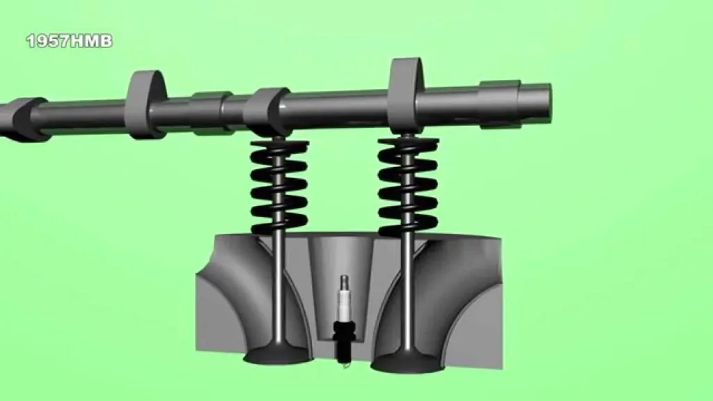
• С верхним валом — роликовой цепью. Относительно низкий уровень шума, простая конструкция, небольшая масса, но схема изнашивается и растягивается. Через зубчатый ремень на неопреновой основе, армированный стальной проволокой и покрытый износостойким нейлоновым слоем. Простая конструкция, бесшумная работа.
3.3. Схема газораспределения:
Суммарное сечение потока, предусмотренное для прохождения газов через клапан, зависит от продолжительности его открытия. Как известно, в четырехтактных двигателях для реализации тактов впуска и выпуска предусмотрен один ход поршня, соответствующий повороту коленчатого вала на 180˚. Однако опыт показал, что для лучшего наполнения и очистки цилиндра необходимо, чтобы продолжительность процессов наполнения и опорожнения была больше, чем соответствующие ходы поршня, т.е. открытие и закрытие клапанов должно производиться не в мертвых точках хода поршня, а с некоторым обгоном или задержкой.
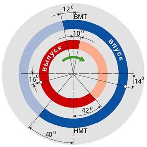
Моменты открытия и закрытия клапанов выражаются в углах поворота коленчатого вала и называются фазами газораспределения. Для большей надежности эти фазы выполнены в виде круговых диаграмм (рис. 1).
Всасывающий клапан обычно открывается с углом обгона φ1 = 5˚ — 30˚ до того, как поршень достигает верхней мертвой точки. Это обеспечивает определенное поперечное сечение клапана в самом начале такта наполнения и, таким образом, улучшает наполнение цилиндра. Закрытие всасывающего клапана выполняется с углом задержки φ2 = 30˚ — 90˚ после прохождения поршнем нижней мертвой точки. Задержка закрытия впускного клапана позволяет использовать скорость всасываемой свежей топливной смеси для улучшения заправки и, следовательно, увеличения мощности двигателя.
Открытие выпускного клапана производится с углом обгона φ3 = 40˚ — 80˚, т.е. в конце хода, когда давление в газах цилиндра относительно высокое (0,4 — 0,5 МПа). Интенсивный выброс газового баллона, начатый при этом давлении, приводит к быстрому падению давлений и их температуры, что значительно снижает работу по вытеснению рабочих газов. Выпускной клапан закрывается с углом задержки φ4 = 5˚ — 45˚. Эта задержка обеспечивает хорошую очистку камеры сгорания от выхлопных газов.
Диагностика, обслуживание, ремонт:
4.1. Диагностика
Диагностические признаки:
- •Пониженная мощность двигателя внутреннего сгорания:
- Уменьшенный зазор;
- Неполное прилегание клапанов;
- Заклинивание клапанов.
• Повышенный расход топлива: - Уменьшенный зазор между клапанами и подъемниками;
- Неполное прилегание клапанов;
- Заклинивание клапанов.
• Износ в двигателях внутреннего сгорания: - Износ распредвалов;
- вскрытие кулачков распредвала;
- Увеличенный зазор между стержнями клапанов и их втулками;
- Большой зазор между клапанами и подъемниками;
- перелом, нарушение эластичности пружин клапана.
• Низкий показатель давления: - Седла клапанов мягкие;
- Мягкая или сломанная пружина клапана;
- Прогоревший клапан;
- сгоревшая или порванная прокладка головки блока цилиндров;
- Неотрегулированный тепловой зазор.
• Высокий показатель давления. - Уменьшена высота головы;
Методы диагностики ГРМ :
• Измерение давления в цилиндре в конце такта сжатия. Во время измерения должны быть соблюдены следующие условия: двигатель внутреннего сгорания должен быть нагрет до рабочей температуры; Свечи зажигания необходимо демонтировать; Центральный кабель индукционной катушки должен быть смазан маслом, а дроссельная заслонка и воздушный клапан должны быть открыты. Измерение выполняется с помощью компрессоров. Разница давлений между отдельными цилиндрами не должна превышать 5%.
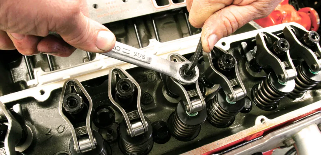
4.2. Регулировка теплового зазора в ремне ГРМ:
Проверка и регулировка теплового зазора производится с помощью пластин манометра в последовательности, соответствующей порядку работы двигателя, начиная с первого цилиндра. Зазор считается отрегулированным должным образом, если толщиномер с толщиной, соответствующей нормальному зазору, проходит свободно. При регулировке зазора удерживайте регулировочный винт отверткой, ослабьте контргайку, поместите пластину зазора между штоком клапана и муфтой и поверните регулировочный винт, чтобы установить требуемый зазор. Затем контргайка затягивается.
4.3. Ремонт клапанной группы:
• Ремонт клапана — основными неисправностями являются износ и прогорание конической рабочей поверхности, износ штока и появление трещин. Если головки горят или появляются трещины, клапаны утилизируются. Изогнутые штоки клапанов выпрямляются на ручном прессе с помощью приспособления. Изношенные штоки клапанов ремонтируются путем хронизации или глажки, а затем шлифуются до номинального или увеличенного ремонтного размера. Изношенная рабочая поверхность клапанной головки шлифуется до ремонтного размера. Клапаны притираются к седлам с помощью абразивных паст. Точность помола проверяют заливкой керосина на навесные вентили, если он не протекает, то 4-5 минут помол хороший. Пружины клапанов не восстанавливают, а заменяют на новые.
Вопросы и ответы:
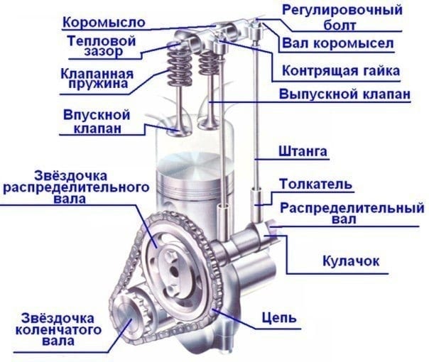
Что входит в газораспределительный механизм? Он находится в головке блока цилиндров. В его конструкцию входит: постель распредвала, распредвал, клапаны, коромысла, толкатели, гидрокомпенсаторы и в некоторых моделях фазовращатель.
Для чего служит ГРМ двигателя? Этот механизм обеспечивает своевременную подачу свежей порции воздушно-топливной смеси и отвод отработавших газов. В зависимости от модификации может изменять момент фаз газораспределения.
Где располагается газораспределительный механизм? В современном двигателе внутреннего сгорания газораспределительный механизм находится над блоком цилиндров в головке блока цилиндров.