Hall sensor: principle of operation, types, application, how to check
Content
- What is a Hall sensor in a car
- What is a Hall sensor in a car for?
- Briefly about the principle of work
- Where is it located and what does it look like?
- Устройство
- Types and scope
- Linear (analogue) Hall sensors
- Digital Hall Sensors
- Appointment of HH in the car ignition system
- Ignition with Hall sensor
- Benefits of Automotive Hall Sensor
- Hall sensor applications
- What malfunctions can there be?
- Sensor check
- Trouble-shooting
- How to replace the sensor with your own hands?
- Related videos
- Questions and answers:
For the efficient operation of all systems of a modern car, manufacturers equip the vehicle with a variety of electronic devices that have more advantages over mechanical elements.
Each sensor is of great importance for the stability of the operation of various components in the machine. Consider the features of the hall sensor: what types are there, the main malfunctions, the principle of operation and where it is applied.
What is a Hall sensor in a car
A hall sensor is a small device that has an electromagnetic principle of operation. Even in old cars of the Soviet automobile industry, these sensors are available - they control the operation of the gasoline engine. If a device malfunctions, the engine will lose stability at best.
They are used for the operation of the ignition system, the distribution of phases in the gas distribution mechanism and others. To understand what malfunctions are related to the breakdown of the sensor, you need to understand its structure and principle of operation.
What is a Hall sensor in a car for?
A hall sensor in a car is needed to record and measure magnetic fields in different parts of the car. The main application of HH is in the ignition system.
The device allows you to determine specific parameters in a non-contact way. The sensor creates an electrical impulse that goes to the switch or ECU. Further, these devices send a signal to generate a current to create a spark in the candles.
Briefly about the principle of work
The principle of operation of this device was discovered in 1879 by the American physicist E.G. Hall. When a semiconductor wafer enters the area of the magnetic field of a permanent magnet, a small current is generated in it.
After the termination of the magnetic field, no current is generated. The interruption of the influence of the magnet occurs through the slots in the steel screen, which is placed between the magnet and the semiconductor wafer.
Where is it located and what does it look like?
The Hall effect has found applications in many vehicle systems such as:
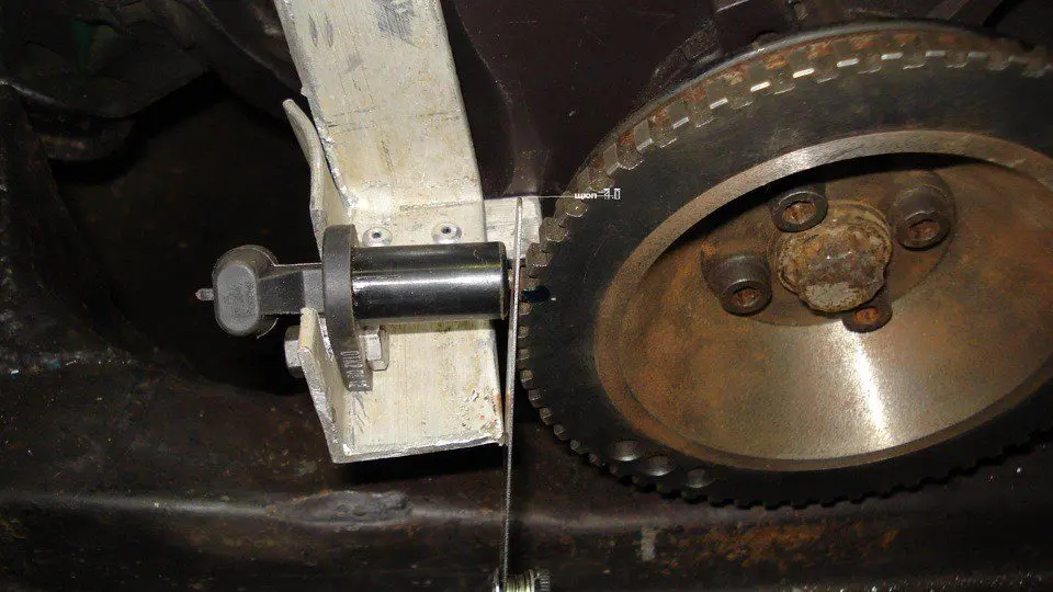
- Determines the position of the crankshaft (when the piston of the first cylinder is at top dead center of the compression stroke);
- Determines the position of the camshaft (to synchronize the opening of valves in the gas distribution mechanism in some models of modern internal combustion engines);
- In the ignition system breaker (on the distributor);
- In the tachometer.
In the process of rotation of the motor shaft, the sensor reacts to the size of the slots of the teeth, from which a low voltage current is generated, which is supplied to the switching device. Once in the ignition coil, the signal is converted into high voltage, which is needed to create a spark in the cylinder. If the crankshaft position sensor is defective, the engine cannot be started.
A similar sensor is located in the breaker of the contactless ignition system. When it is triggered, the windings of the ignition coil are switched, which allows it to produce a charge on the primary winding and discharge from the secondary.
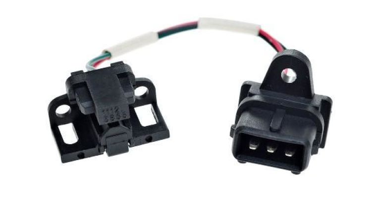
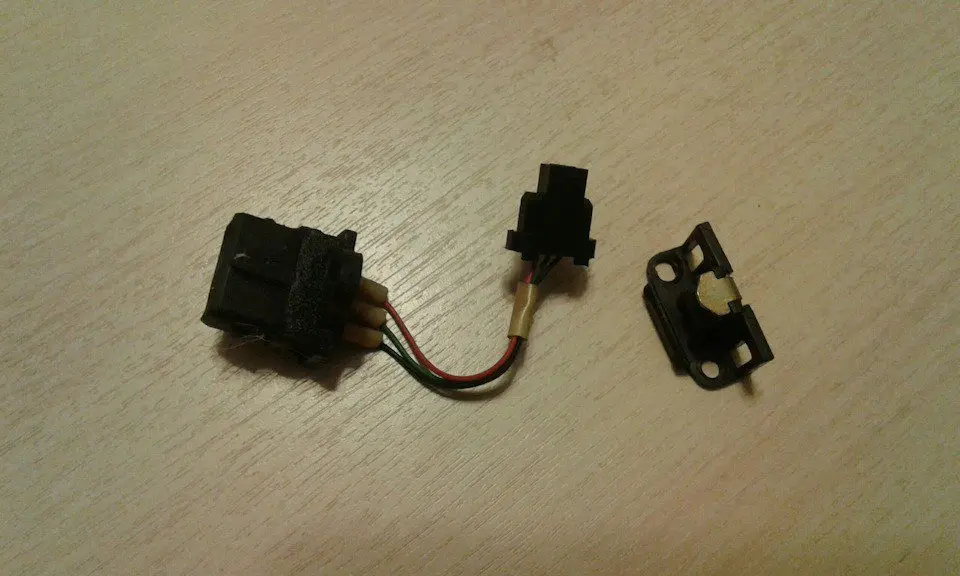
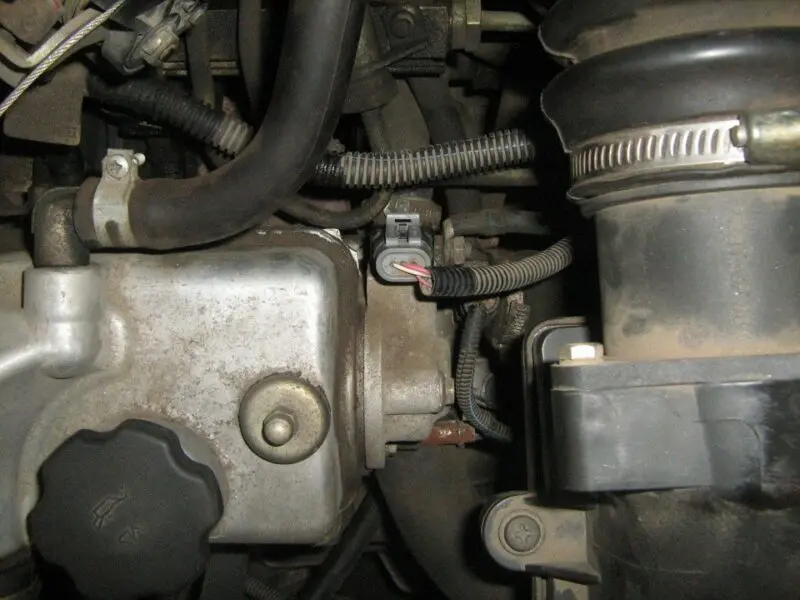
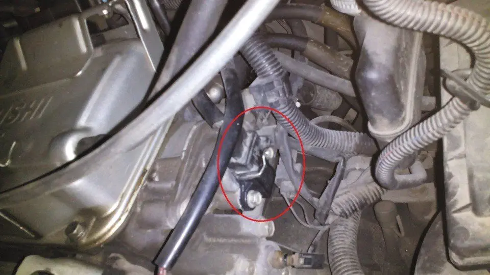
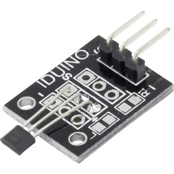
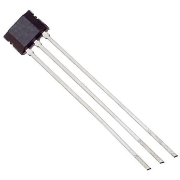
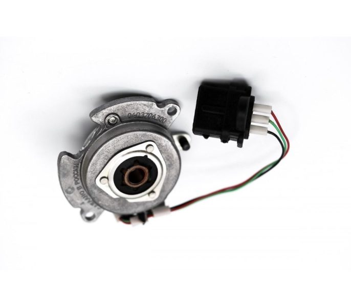
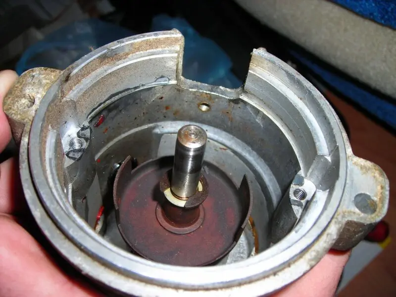
The photo below shows what the sensor looks like and where it is installed in some vehicles.
Устройство
A simple hall sensor device consists of:
- Permanent magnet. It creates a magnetic field that acts on the semiconductor, in which a low voltage current is created;
- Magnetic circuit. This element perceives the action of a magnetic field and generates a current;
- Rotating rotor. It is a metal curved plate that has slots. When the shaft of the main device rotates, the rotor blades alternately block the effect of the magnet on the rod, which creates impulses inside it;
- Plastic enclosures.
Types and scope
All Hall sensors fall into two categories. The first category is digital and the second is analog. These devices are successfully used in various industries, including the automotive industry. The simplest example of this sensor is DPKV (measures the position of the crankshaft as it rotates).
In other industries, similar devices are used, for example, in washing machines (laundry is weighed based on the speed of rotation of a full drum). Another common application of such devices is in a computer keyboard (small magnets are located on the back of the keys, and the sensor itself is installed under an elastic polymer material).
Professional electricians use a special device for contactless measurement of the current in the cable, in which a Hall sensor is also installed, which reacts to the strength of the magnetic field created by the wires and gives a value corresponding to the strength of the magnetic vortex.
In the automotive industry, Hall sensors are integrated into various systems. For example, in electric vehicles, these devices monitor the battery charge. Crankshaft position, throttle valve, wheel speed, etc. - all this and many other parameters are determined by the Hall sensors.
Linear (analogue) Hall sensors
In such sensors, the voltage directly depends on the strength of the magnetic field. In other words, the closer the sensor is to the magnetic field, the higher the output voltage. These types of devices do not have a Schmidt trigger and a switching output transistor. The voltage in them is taken directly from the operational amplifier.
The output voltage of analog Hall effect sensors can be generated either by a permanent magnet or an electric magnet. It also depends on the thickness of the plates and the strength of the current that flows through this plate.
Logic dictates that the output voltage of the sensor can be increased indefinitely with increasing magnetic field. Actually it is not. The output voltage from the sensor will be limited by the supply voltage. The peak output voltage across the sensor is called the saturation voltage. When this peak is reached, it is pointless to continue to increase the magnetic flux density.
For example, current clamps work on this principle, with the help of which the voltage in the conductor is measured without contact with the wire itself. Linear Hall sensors are also used in devices that measure magnetic field density. Such devices are safe to use, since they do not require direct contact with a conductive element.
An example of using an analog element
The figure below shows a simple circuit of a sensor that measures current strength and works on the principle of the Hall effect.
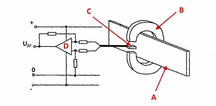
Such a current sensor works very simply. When current is applied to a conductor, a magnetic field is created around it. The sensor captures the polarity of this field and its density. Further, a voltage corresponding to this value is formed in the sensor, which is supplied to the amplifier and then to the indicator.
Digital Hall Sensors
Analog devices are triggered depending on the strength of the magnetic field. The higher it is, the more voltage will be in the sensor. Since the introduction of electronics into various control devices, the hall sensor has acquired logical elements.
The device either detects the presence of a magnetic field, or does not detect it. In the first case, it will be a logical unit, and a signal is sent to the actuator or control unit. In the second case (even with a large, but not reached the limit threshold, magnetic field), the device does not record anything, which is called a logical zero.
In turn, digital devices are of the unipolar and bipolar types. Let's briefly consider what their differences are.
Unipolar
As for the unipolar variants, they are triggered when a magnetic field of only one polarity appears. If you bring a magnet with opposite polarity to the sensor, the device will not react at all. Deactivation of the device occurs when the strength of the magnetic field decreases or it disappears altogether.
The required unit of measurement is issued by the device at the moment when the strength of the magnetic field is maximum. Until this threshold is reached, the device will show a value of 0. If the magnetic field induction is small, the device is not able to fix it, therefore, it shows a zero value. Another factor that affects the accuracy of measurements by the device is its distance from the magnetic field.
Bipolar
In the case of the bipolar modification, the device is activated when the electromagnet creates a specific pole, and is deactivated when the opposite pole is applied. If the magnet is removed while the sensor is on, the device will not turn off.
Appointment of HH in the car ignition system
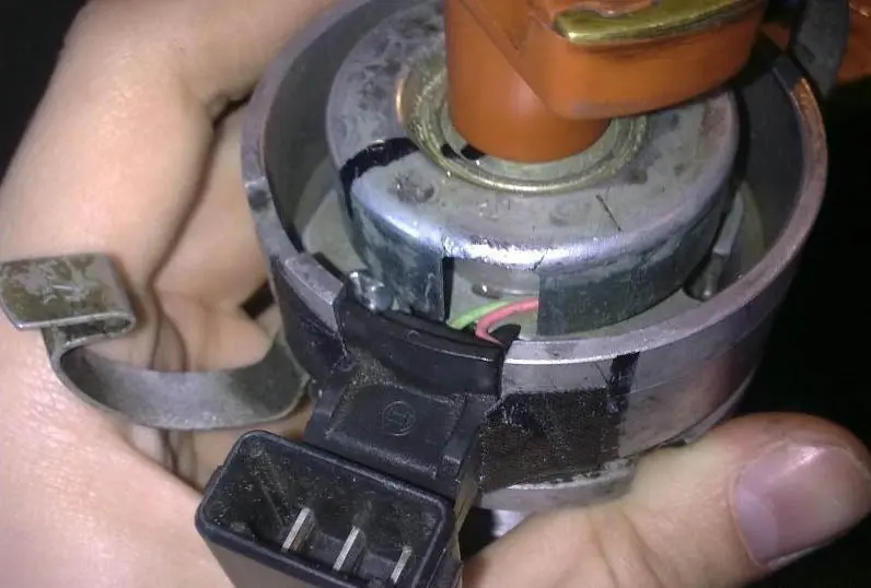
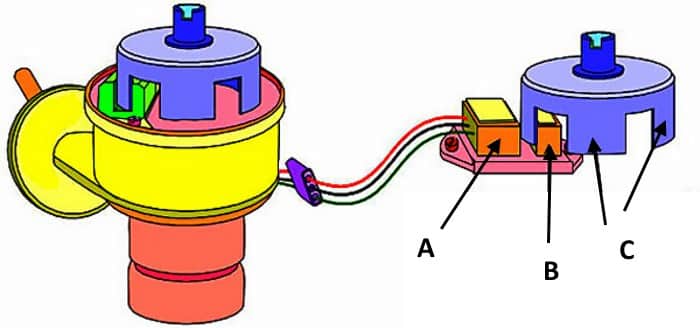
Hall sensors are used in non-contact ignition systems. In them, this element is installed instead of the breaker slider, which turns off the primary winding of the ignition coil. The figure below shows an example of a Hall sensor, which is used in cars of the VAZ family.
In more modern ignition systems, the Hall sensor is used only to determine the position of the crankshaft. Such a sensor is called a crankshaft position sensor. The principle of its operation is identical to the classic Hall sensor.
Only for the interruption of the primary winding and the distribution of the high-voltage pulse is already the responsibility of the electronic control unit, which is programmed for the characteristics of the engine. The ECU is able to adapt to different operating modes of the power unit by changing the ignition timing (in contact and non-contact systems of the old model, this function is assigned to the vacuum regulator).
Ignition with Hall sensor
In contactless ignition systems of the old model (the on-board system of such a car is not equipped with an electronic control unit), the sensor works in the following sequence:
- The distributor shaft rotates (connected to the camshaft).
- A plate fixed on the shaft is located between the Hall sensor and the magnet.
- The plate has slots.
- When the plate rotates and a free space is formed between the magnet, a voltage is generated in the sensor due to the influence of the magnetic field.
- The output voltage is supplied to the switch, which provides switching between the windings of the ignition coil.
- After the primary winding is turned off, a high-voltage pulse is generated in the secondary winding, which enters the distributor (distributor) and goes to a specific spark plug.
Despite the simple scheme of operation, a contactless ignition system must be perfectly tuned so that a spark appears in each candle at the right time. Otherwise, the motor will run unstable or not start at all.
Benefits of Automotive Hall Sensor
With the introduction of electronic elements, especially in systems that require fine tuning, engineers have been able to make systems more stable compared to counterparts that are controlled by mechanics. An example of this is the contactless ignition system.
The Hall effect sensor has several important advantages:
- It is compact;
- It can be installed absolutely in any part of the car, and in some cases even directly in the mechanism itself (for example, in a distributor);
- There are no mechanical elements in it, so that its contacts do not burn, as, for example, in a contact ignition system breaker;
- Electronic pulses respond much more effectively to changes in the magnetic field, regardless of the speed of rotation of the shaft;
- In addition to reliability, the device provides a stable electrical signal in different modes of operation of the motor.
But this device also has significant drawbacks:
- The biggest enemy of any electromagnetic device is interference. There are plenty of them in any engine;
- Compared to a conventional electromagnetic sensor, this device will be much more expensive;
- Its performance is affected by the type of electrical circuit.
Hall sensor applications
As we said, Hall principle devices are used not only in cars. Here are just a few of the industries where a Hall effect sensor is either possible or required.
Linear sensor applications
Linear type sensors are found in:
- Devices that determine the current strength in a non-contact way;
- Tachometers;
- Vibration level sensors;
- Ferromagnet sensors;
- Sensors that determine the angle of rotation;
- Non-contact potentiometers;
- DC brushless motors;
- Working substance flow sensors;
- Detectors that determine the position of working mechanisms.
Application of digital sensors
As for digital models, they are used in:
- Sensors that determine the frequency of rotation;
- Synchronization devices;
- Ignition system sensors in the car;
- Position sensors of elements of working mechanisms;
- Pulse counters;
- Sensors that determine the position of the valves;
- Door locking devices;
- Working substance consumption meters;
- Proximity sensors;
- Contactless relays;
- In some models of printers as sensors that detect the presence or position of paper.
What malfunctions can there be?
Here is a table of the main hall sensor malfunctions and their visual manifestations:
| Malfunction: | How does it manifest: |
| The sensor is triggered more often than the crankshaft goes through a full cycle | Fuel consumption increases (while other systems, such as fuel, are working properly) |
| The device is triggered every time or periodically turns off completely | While the car is moving, the engine may stall, the car jerks, engine power drops, it is impossible to accelerate the car faster than 60 km / h. |
| Hall sensor malfunction | In some foreign cars of the latest generation, the gear lever is blocked |
| The crankshaft position sensor is broken | Motor cannot be started |
| Errors in an electrical system in which the hall sensor is the main element | On the dashboard, the error light of the self-diagnosis system of a specific unit, for example, the engine at idle speed, lights up, but disappears when the engine picks up speed. |
It often happens that the sensor itself is serviceable, but it feels like it is out of order. Here are the reasons for this:
- Dirt on the sensor;
- Broken wire (one or more);
- Moisture has got on the contacts;
- Short circuit (due to moisture or damage to the insulation, the signal wire shorted to ground);
- Violation of cable insulation or screen;
- The sensor is not connected correctly (polarity is reversed);
- Problems with high voltage wires;
- Violation of the auto control unit;
- The distance between the elements of the sensor and the controlled part is incorrectly set.
Sensor check
To be sure that the sensor is faulty, a check must be performed before replacing it. The easiest way to diagnose a problem - whether the problem is really in the sensor - is to run diagnostics on the oscilloscope. The device not only detects malfunctions, but also indicates an imminent breakdown of the device.
Since not every motorist has the opportunity to carry out such a procedure, there are more affordable ways to diagnose the sensor.
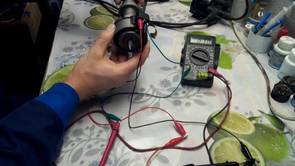
Diagnostics with a multimeter
First, the multimeter is set to DC current measurement mode (switch for 20V). The procedure is performed in the following sequence:
- The armored wire is disconnected from the distributor. It is connected to the mass so that, as a result of diagnostics, you do not accidentally start the car;
- The ignition is activated (the key is turned all the way, but do not start the engine);
- The connector is removed from the distributor;
- The negative contact of the multimeter is connected to the mass of the car (body);
- The sensor connector has three pins. The positive contact of the multimeter is connected to each of them separately. The first contact should show a value of 11,37V (or up to 12V), the second should also show in the 12V region, and the third should be 0.
Next, the sensor is checked in operation. To do this, you need to do the following:
- From the wire entry side, metal pins (for example, small nails) are inserted into the connector so that they do not touch each other. One is inserted into the center contact, and the other into the negative wire (usually white);
- The connector slides over the sensor;
- The ignition turns on (but we don't start the engine);
- We fix the minus contact of the tester on the minus (white wire), and the plus contact to the central pin. The working sensor will give a reading of approximately 11,2V;
- Now the assistant must crank the crankshaft with the starter several times. The multimeter reading will fluctuate. Note the minimum and maximum values. The lower bar should not exceed 0,4V, and the upper one should not fall below 9V. In this case, the sensor can be considered serviceable.
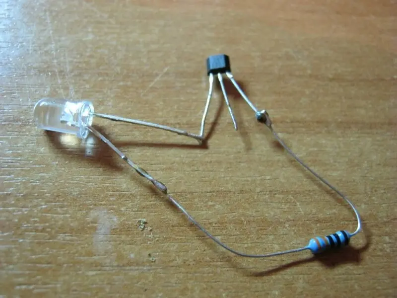
Resistance test
To measure resistance, you will need a resistor (1 kΩ), a diode lamp and wires. A resistor is soldered to the leg of the light bulb, and a wire is connected to it. The second wire is fixed to the second leg of the light bulb.
The check is performed in the following sequence:
- Remove the distributor cover, disconnect the block and contacts of the distributor itself;
- The tester is connected to terminals 1 and 3. After activating the ignition, the display should show a value in the range of 10-12 volts;
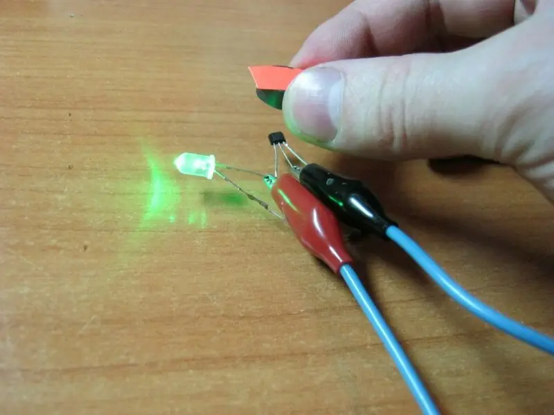
- In the same way, a light bulb with a resistor is connected to the distributor. If the polarity is correct, the control will light up;
- After that, the wire from the third terminal is connected to the second. Then the assistant turns the motor with the help of the starter;
- A blinking light indicates a working sensor. Otherwise, it must be replaced.
Creating a Simulated Hall Controller
This method allows you to diagnose the hall sensor in the absence of a spark. The strip with contacts is disconnected from the distributor. The ignition is activated. A small wire connects the output contacts of the sensor to each other. This is a kind of hall sensor simulator that created the impulse. If, at the same time, a spark has formed on the central cable, then the sensor is out of order and it needs to be replaced.
Trouble-shooting
If you want to repair the hall sensor with your own hands, you first need to purchase a so-called logical component. It can be selected in accordance with the model and type of sensor.
The repair itself is carried out as follows:
- A hole is made in the center of the body with a drill;
- With a clerical knife, the wires of the old component are cut, after which grooves are laid for new wires that will be connected to the circuit;
- The new component is inserted into the housing and connected to the old pins. You can check the correctness of the connection using a control diode lamp with a resistor on one contact. Without the influence of the magnet, the light should go out. If this does not happen, then you need to change the polarity;

- New contacts must be soldered to the device block;
- To make sure that the work is done correctly, you should diagnose the new sensor using the above methods;
- Finally, the housing must be sealed. To do this, it is better to use heat-resistant glue, since the device is often exposed to high temperatures;
- The controller is assembled in reverse order.
How to replace the sensor with your own hands?
Not every car enthusiast has time to manually repair sensors. It's easier for them to buy a new one and install it instead of the old one. This procedure is performed as follows:
- First of all, you need to remove the terminals from the battery;
- The distributor is removed, the block with wires is disconnected;
- The cover of the distributor is removed;
- Before completely dismantling the device, it is important to remember how the valve itself was located. It is necessary to combine the timing marks and the crankshaft;
- The distributor shaft is removed;
- The hall sensor itself is disconnected;
- A new one is installed in place of the old sensor;
- The block is assembled in reverse order.
The latest generation sensors have a long service life, so frequent device replacement is not required. When servicing the ignition system, you must also pay attention to this tracking device.
Related videos
In conclusion, a detailed overview of the device and the principle of operation of the Hall sensor in a car:

Questions and answers:
What is a Hall Sensor? This is a device that reacts to the appearance or absence of a magnetic field. Optical sensors have a similar principle of operation, which react to the impact of a light beam on a photocell.
Where is the hall sensor used? In cars, this sensor is used to detect the speed of a wheel or a specific shaft. Also, this sensor is installed in those systems in which it is important to determine the position of a particular shaft for synchronization of different systems. An example of this is the crankshaft and camshaft sensor.
How to check a Hall sensor? There are several ways to check the sensor. For example, when there is power in the ignition system, and the spark plugs do not emit a spark, on machines with a contactless distributor, the distributor cover is removed and the plug block is removed. Next, the ignition of the car is turned on and contacts 2 and 3 are closed. The high-voltage wire must be kept near the ground. At this moment, a spark should appear. If there is a spark, but there is no spark when connecting the sensor, then it must be replaced. The second way is to measure the output voltage of the sensor. In good condition, this indicator should be in the range from 0.4 to 11V. The third method is to put a known working analog instead of the old sensor. If the system works, then the problem is in the sensor.
2 comment
anonym
I am looking for the electronic diagram ru 3 contact sensor. it is 300 ohms between two pins and the motor no longer starts.
no ignition. testing of two other coils. same result. testing of another injection unit. still no ignition. yet it is two double coils. there is no distributor on the peugeot 106.
Nguyen Duy Hoa
Why is the optical and electromagnetic hall called the G NE ignition sensor?